Our Services

OUR SERVICES

Pranetra Manpower solutions's Benefits

We offer a full range of solutions to power your business strategy. With unparalleled expertise and breadth of offerings,Pranetra Manpower solutions optimizes total talent management across your entire workforce to deliver measurable results and business success.

Setting up of Steel Re-Rolling Mills

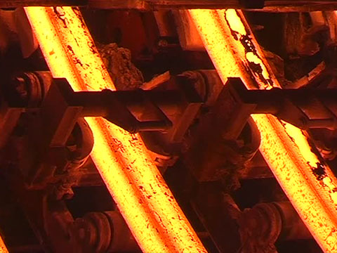
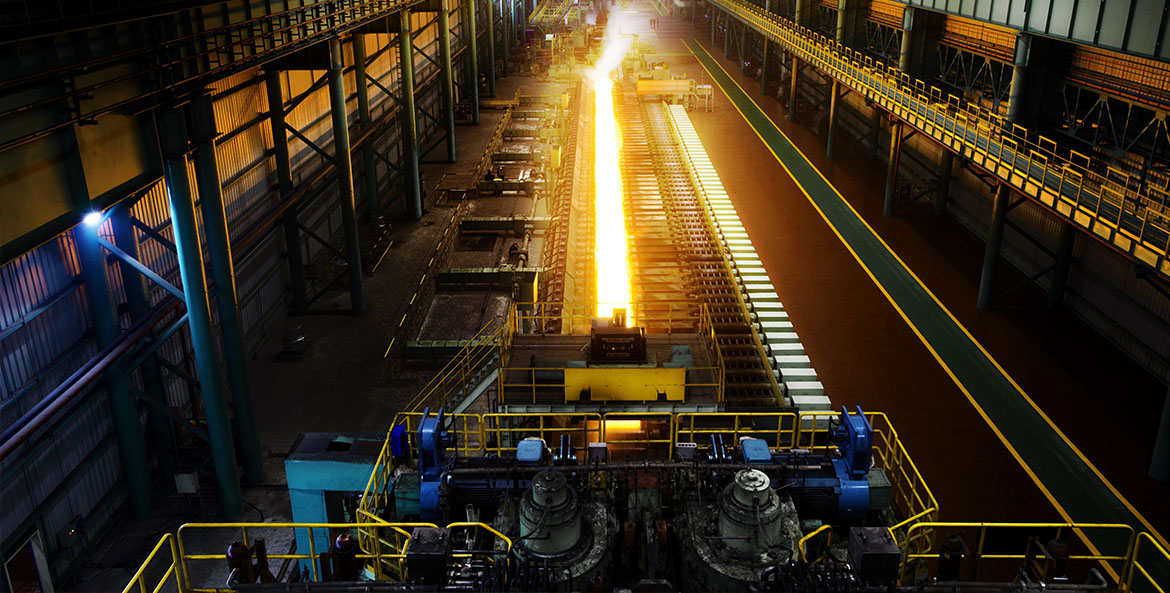
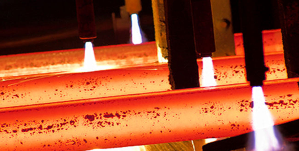
Pranetra MS specialises in setting up of Hot Steel Rolling Mill Plants and its equipments. With our expertise our clients have become leading Wire Rolling Mill manufacturer, TMT Bar Rolling Mill manufacturer, Structure Rolling Mill manufacturer, Bar Rolling Mill manufacturer, Steel Rolling Mill Machinery manufacturer, Steel Rolling Mill Plants supplier, Chill Type Roll manufacturer.
No two organizations are ever alike. That’s why our expert recruiters dig deep to understand your organization and the job skills necessary for success. We use proven sourcing strategies to identify where the talent is and how best to attract them. Our experience and expertise accelerates the acquisition of the right talent for you.

Setting up of Steel melting shops / Mini Steel Plants -

Pranetra MS has vast experience in designing, erection of steel making (SMS) plants. We highly concentrate at the quality hence we provide our customers valuable products at reasonable prices with facilitations & services as consultancy, plant designs & layouts. Pranetra MS also resources complete used SMS plants / furnaces / CCM for its clients

Help in running / modernization of an existing steel plant and rolling mills -

Pranetra MS have experience and expertise in running / modernizatio, buying and selling of working steel rolling mills and mini steel plants in India and abroad. Pranetra MS undertakes the production contracts of steel mills and also arrange experienced manpowers for the existing and new steel projects

Innovative Workforce Solutions

Recruitment Process Outsourcing (RPO) Our Recruitment Process Outsourcing offering sources and attracts talent through our flexible and scalable recruitment solutions which can include anything from sourcing and selection to onboarding. Built upon our deep recruiting expertise and based on our rigorous process, our innovative approach ensures the results you need — greater predictability of cost, a more efficient recruiting process, an improved candidate experience, and more importantly, improved talent quality. Our high-performance recruiters focus on finding the best candidate for each job, saving you time, energy and money, while improving hiring efficiencies

Pranetra MS is a reliable Consultancy company, providing complete solution and unmatched steel plant advisory services. Pranetra MS has played a significant role in development of Indian steel industry over the years and have acquired vast experience in conceptual planning, design and engineering of steel making, secondary metallurgy, continuous casting, Ferro-alloys and steel Re-Rolling Mills. Pranetra MS, with the support of it's multi disciplinary team of well experienced engineers, rendering its services in all spheres of activities in steel making.


The knowledge gained in steel led to the formation of consultancy company , to provide wide range of consultancy and engineering services to the steel, non ferrous metal and other industries in India and abroad.
Pranetra MS, an ISO certified company, offers highest quality services from concept to commissioning to its clients across the world. Pranetra MS undertakes Green field projects on Consultancy / Turnkey basis, provides Design, Detail Engineering, Technical, Management, Training, Recruitment and Erection & Installation services to steel industries for the manufacturing of sponge iron, hot briquette iron(HBI), steel billets / ingots, rolling mill (long) products, large diameter pipes (ERW, HSAW, LSAW). Pranetra MS also undertakes Erection & Installation of Induction Furnace (IF), Electric Arc Furnace (EAF), Continuous Casting Machine (CCM) and other Auxiliary Equipments of steel making.
In addition to successful completion of projects in India, Pranetra MS also has satisfied clients in Egypt, Saudi Arab, Iran, Bangladesh, Nepal, Azerbaijan, and Sri Lanka..


Design & Engineering Services
  • Feasibility studies
  • Bankable Project Proposals
  • Detailed Project Reports
  • Basic Engineering
  • Detail Engineering
  • Instrumentation and Automation
Project Management Services
  • Plant Erection and Construction
  • Procurement and Inspection
  • Project Planning, Monitoring and Supervision
  • Start-up, Testing and Commissioning
Management Services
  • Total Quality Management and ISO: 9001 Certification Assistance
  • Corporate Planning
  • Benchmarking
  • Corporate Restructuring
  • Marketing and Distribution
  • Software Development and System Design
Technical Services
  • Plant Operation and Maintenance
  • Technology Up-gradation
  • Quality, Productivity and Performance Improvement
  • Environment Management and Pollution Control
  • Energy Conservation & Audit
HR and Training Services
  • Recruitment Services
  • Training for Operation, Maintenance and Management of Steel and Power plants
  • Engineering and Technical Skills Training
  • Environment Management and Pollution Control
  • Development Programmes

Range of More services :-

Consultancy
  • Feasibility report and detailed project report
  • Consultancy for setting up green field steel melting shop, continuous casting plant, Ferro alloys shop & Re-Rolling Mills
  • Consultancy for modernization, revamping and shifting of existing plants
  • Project planning and monitoring
  • Optimization and health study
  • Asset evaluation
  • Energy audit and environmental studies

Engineering
  • Auxiliary steel melting shop equipments
  • Complete services and utilities
  • Material handling facilities
  • Civil and structural work
  • Gas cleaning and fume extraction system
  • Relocation of plant and equipment

Supply and site services
  • Turnkey supply of steel melting shop, continuous casting plant & Rolling Mills
  • Supervision of construction, erection and commissioning

We leverage our research and unique insights into how organizations and individuals can win in the changing world of work to create and deliver innovative workforce solutions.

OUR SERVICES

For Certian Types Of Employer, The Situation Is An URGENT ONE

Issues like compliance and safety should be on the radars of all employers, regardless of their size, industry or geographical presence. That said, there are certain types of companies for which worker tracking should be an immediate priority based on their relative risk exposure and opportunities to benefit strategically. These include:

Large Multinational Organizations:

Companies with a presence in multiple countries should be especially concerned with legal and compliance issues associated with the laws of different countries. Worker tracking ensures that all external workers have the proper documentation, checks and classifications.

Consultant-Dependent Industries (e.g., IT and Engineering):

It stands to reason that the size of the external workforce would be correlated with a company’s risk level and the likelihood of inaccurate worker tracking taking root. Consider, for example, the technology company that had 400 IT vendors and discovered 1,200 active badges granting access to its facilities

Heavily Regulated Industries:

Organizations in industries such as financial services or defense clearly have deeply rooted interests in confidentiality and compliance. Improper or inaccurate information can threaten the perception of due diligence and potentially threaten standing with regulators.

Companies with Multiple Locations:

Organizations located in a single country but with multiple locations are likely to face many of the departmental and technology alignment issues noted earlier in this paper. They should also have a high interest in the safety issues discussed here—namely in understanding who is present in their buildings and who to contact in the event of an emergency.

Highly Secure Industries:

Those working with sensitive information and heavily guarded IP have an obvious interest in understanding who has access to their resources on any given day

Companies that Use a Large Number of Staffing and/or SOW Vendors:

Just like consultant-dependent industries, those with relatively large numbers of vendors will be more likely to require a comprehensive worker tracking solution that those using only a handful of vendors

WorkerTracking

With a significant number of global contingent workers currently unaccounted for, the scale of the problem may be more significant than people realize. The seriousness of the issue extends beyond current workforces as well. One study1 found that only 44 percent of companies have implemented systems to ensure adequate compliance during off-boarding—meaning that many workers could still have access to facilities and data. Worker tracking paints a clear picture of an organization’s external workforce. At its most basic level, worker tracking seeks to account for all non-employee workers with access to an organization’s facilities, resources and intellectual property. This includes:

  • Temporary workers (typically employed by staffing agencies)
  • Contract workers, consultants and freelancers (typically self-employed)
  • Statement of work labor (typically employed by contracted services firms)

For many companies, a significant portion of this workforce might already be accounted for under a managed service provider (MSP). In that case, worker tracking can supplement an existing MSP to ensure that the entire workforce is captured and strategic decision-making is fully informed. Once a worker tracking solution is fully implemented, companies have visibility into top-level information for all workers including: name, start and end dates, checks and certifications, documentation, vendor association, skills sets, SOW, ID/badge #.

It seems fairly intuitive that companies would desire and seek out this information. This begs the question, “Why aren’t they already doing this?” The answer is simple. Many companies assume their current process is working.
The hypothesis is not that companies undervalue an accurate headcount or the benefits associated with it. Instead, it seems to more frequently be a matter of assuming that current systems are getting the job done. Technology tools like vendor management systems are built to track external vendors and the workforces associated with them. The challenge comes when these systems break down—often because new technology is introduced that doesn’t fully integrate with them or because they aren’t consistently maintained. Once an organization has awareness of the worker tracking issue, there is still an inclination to believe worker tracking can be built into an existing system. The assumption is that a company can develop the right policies and procedures, and everyone will follow them. Of course, this is rarely the case. In practice, the technology exists even when the processes do not.

Our Expertise

Induction furnace

Induction heating is a heating method. The heating by the induction method occurs when an electrically conductive material is placed in a varying magnetic field. Induction heating is a rapid form of heating in which a current is induced directly into the part being heated. Induction heating is a non-contact form of heating.
The heating system in an induction furnace includes:
Induction heating power supply,
Induction heating coil,

Water-cooling source, which cools the coil and several internal components inside the power supply. The induction heating power supply sends alternating current through the induction coil, which generates a magnetic field. Induction furnaces work on the principle of a transformer. An alternative electromagnetic field induces eddy currents in the metal which converts the electric energy to heat without any physical contact between the induction coil and the work piece. A schematic diagram of induction furnace is shown in Figure 16. The furnace contains a crucible surrounded by a water cooled copper coil. The coil is called primary coil to which a high frequency current is supplied. By induction secondary currents, called eddy currents are produced in the crucible. High temperature can be obtained by this method. Induction furnaces are of two types: cored furnace and coreless furnace. Cored furnaces are used almost exclusively as holding furnaces. In cored furnace the electromagnetic field heats the metal between two coils. Coreless furnaces heat the metal via an external primary coil.

CCM Contineous Casting Machine

Continuous casting (CC) is a method of producing an infinite solid strand from liquid steel by continuously solidifying it as it moves through a CC machine. It is the predominant process route in a modern steel plant which links steelmaking and hot rolling. A typical section and plan view of a CC machine is shown in Fig 1.

Types of continuous casting machines

CC machines have evolved from the strictly vertical type of machine to curved machines in order to limit the installation height while still using high casting speeds. In recent years, CC machines of more sophisticated mechanical design are being constructed. These machines apply several techniques for achieving higher casting speeds and higher outputs and are with progressive straightening or progressive bending over a liquid core. The main types of the CC machines which are in operation these days are given below.

  • Simple vertical CC machine with a straight mould and cutoff in the vertical position
  • Vertical CC machine with a straight mould along with single point bending and straightening
  • Vertical CC machine with a straight mould along with progressive bending and straightening
  • Bow type machine with curved mould and straightening
  • Bow type machine with curved mould and progressive straightening

In all cases, the bending and straightening is usually carried out in one or several steps. Multistep bending and straightening reduces the mechanical stresses and reduces the risk of strand cracking. The first CC machine which was built up for CC of liquid steel was a simple vertical CC machine. Then later the development led to many kinds of CC machines with various ways of bending and straightening. The main objective for these developments have been to construct lower and simpler CC machines with smaller need for space, lower investment costs, and high flexibility in production and maintenance. One of the main issues with a vertical CC machine is that the distance between the mould and the point of cutting is limited. Due to this the casting speed is low and low speed means low production rate. The advantage of the vertical CC machine is that there is no bending or straightening of the strand. In the case of large strand sizes, the stress caused by the ferrostatic pressure of the liquid steel inside the strand can lead to bulging of the solidified strand shell.


The high bulging can lead to the formation of severe defects like segregations and cracking. It is therefore very important to support the strand sufficiently to avoid bulging. The higher is the machine, the bigger is the risk for bulging. This is also one reason for the development of the lower machines, i.e., bent or bow-type casters.


One important characteristic in continuous casting is the removal of nonmetallic inclusions from the liquid steel. Owing to their lower density compared to the liquid steel, the inclusions are able to float up from the liquid. In the straight CC machines, the inclusions can float up more easily to the meniscus (liquid surface near the mould wall) than in the bow type CC machines. This is because in the bow type CC machines some inclusions can attach to the inner arc of the strand shell, when they are flowing up. This can be seen as a higher amount of inclusions but also as an uneven distribution of the inclusions in the as cast strand. So, the vertical or vertical bending type CC machines have the advantage that inclusions can float up better to the meniscus than in bow type CC machines. These days, the most common CC machine type is the bow type with curved mould. The strand leaves this curved mold in an arc without the need for bending after the mould and just with straightening at the lower part of the CC machine. In the case of larger strand, especially with slabs, also vertical bending CC machines are today more and more popular, because of the increasing need for cleanness. It is anyhow important to know that many things other than the CC machine design affect the cleanness and steel quality.


The CC machines are normally named according to the strand dimensions such as billet, bloom, and slab CC machines etc. There are also CC machines to cast rounds and other shapes like beam blanks.


Thin slab casting, inline strip casting and near net shape casting (dog bone) are some of the latest development in the field of CC machines. Horizontal CC machines have some advantages of low height and low construction costs over the conventional CC machines. These kinds of CC machines have been used for the continuous casting of many metals such as copper and copper alloys, but for steel, the technology is so complex that it is not widely used for the continuous casting of liquid steel.


The choice between the types of casting machines depends on a complex optimization of the specific facility requirements for the CC machine productivity, product quality, machine complexity, and cost. With the introduction of the newer designs there has been an increasing adoption of the bow type CC machines with curved moulds for CC of slabs and to a lesser extent for CC of billets and blooms. Curved CC machines are normally simpler to build (lower cost) and maintain than vertical with bending machines, as the bender is eliminated. However, for some grades of steel, for example, plate grades, quality and casting speed limitations were previously more restrictive on these curved machines. Recently, with the technological developments of clean steel practices and electromagnetic stirring, curved CC machines have overcome these restrictions. In general, the complexity of the casting process and machine varies greatly between the types of product being cast (billet, bloom, or slab et.). This is due to the thermo mechanical characteristics of the cast sections, and to the different applications of the cast product.


Billet sections are self?supporting in the secondary cooling zone, while slabs are usually not. Usually, billet CC machines have tended to be simple in design, with open pouring streams, limited automatic controls, and no roll support in the secondary cooling zone. On the other hand, slab CC machines are complex and use the total range of subsystems such as total stream shrouding, computer controls, and total roll containment throughout the CC machine. Bloom CC machines are intermediate between these two extremes.


Continuous casting machine equipment

The main equipments of a CC machine constitute (i) ladle turret along with turret weighing system and ladle cover manipulator, (ii) tundish and tundish car along with tundish weighing system, tundish preheater and dryer, (iii) mould and mould oscillation along with mould level control and electromagnetic stirrer, (iv) secondary cooling consisting of strand cooling, strand containment and guiding, (v) withdrawal and straightener, (vi) dummy bar, dummy bar parking and dummy bar disconnect roll unit, (vii) pinch roll and torch cut off unit, (viii) Product identification system, and (ix) Roller table and product discharge system. Some of these equipments are described in more detail below.


Ladle turret

One very important part of a CC machine is the ladle turret. It is mounted at the reinforced concrete base. It holds the steel teeming ladles, which can weigh up to 300 t. By means of the ladle turret, the steel teeming ladles are alternately slewed into pouring and charging position. This function ensures the uninterrupted operation of the CC machine. While one ladle is being emptied, a full ladle is provided on the other side.

The bearings in the ladle turret, in spite of being subjected to high forces and considerable tilting moments, reach service lives of more than 10 years.
Ladle turret supports the ladles and its hydraulic system with rotary arms has the mechanism to allow the ladles to be raised and lowered whilst maintaining a horizontal position. Also strain gauge load cell is incorporated in the ladle turret to allow the weight of the ladles to be continuously monitored. Variable frequency AC motor is normally used for the transmission mechanism. Ladle turret usually has emergency response mechanism available for ensuring the safety of operators in an emergency. It also generally has manhole which ensures its easy maintenance. It is also normally equipped with the ladle cover manipulator.

Tundish

The main functions of the tundish are to be a steel reservoir between the steel teeming ladle and the mould, and in the case of multi strand CC machines to distribute the liquid steel into the different moulds. The first item is of special importance during the ladle change. In addition to being a reservoir of liquid steel, the tundish is more increasingly being used as a metallurgical reactor vessel aimed at improving control of steel cleanliness, temperature, and composition.

Tundishes are usually of an elongated, geometrically simple shape. There are many types and shapes of tundish. One common tundish design for multi strand billet and bloom CC machines is a trough shape with a pouring box offset at the midpoint while for the slab CC machines the tundish is a short box or of a tub shape. The pouring stream from the ladle is directed downward to a position in the tundish bottom which is protected with a wear resistant pouring pad. This position is usually as far as possible from the tundish nozzle to minimize turbulence. In other locations, the tundish is lined with refractory bricks or boards. Weirs and dams are used as flow control devices which both increase the residence time as well as reduce the detrimental effects of turbulence on the liquid steel surface, the liquid steel streams entering the mould and dead zones.

Nozzles for protecting the pouring stream against reoxidation between ladle and tundish and tundish and mould are used nowadays almost on all the CC machines, at least when casting high grade steels. Both stopper controlled nozzles and slide gates of various designs are used to control the steel flow from the ladle to the tundish and from the tundish to the mould. The free surface of the liquid steel in tundish is generally covered with slag to avoid reoxidation and heat losses from the liquid steel.

The discharge rate of liquid steel is controlled by the bore of the nozzle and the ferrostatic pressure (height of liquid steel in the tundish) above the nozzle. Different bores are selected depending on the section size being cast and casting speed required. Stopper rod controlled nozzles are used for casting slabs and large sections when aluminum killed steels are produced. In this application, discharge rate of liquid steel through the nozzle is controlled manually or automatically by the setting of the stopper head in relation to the nozzle opening. Earlier oversized nozzles were used for casting aluminum killed steels because of the buildup of alumina so that the stopper head could be raised to compensate for a reduction in flow rate.

Recent developments in deoxidation practices together with the use of argon bubbling through the stopper head and nozzle units have minimized the alumina buildup problem. Another development in controlling liquid steel flow from the tundish is the application of slide gate systems which are similar to those employed on ladles. These gate systems can also provide the capability for changing nozzles during casting as well as changing nozzle size.

Tundish car usually adopts the half suspended design and is mounted at the main operating platform. It is usually hydraulic powered and is used to support and convey the tundish for casting or heating. It also incorporates weighing mechanism for the weight measurement to allow the weight of liquid steel to be continuously monitored.

Mould

The mould is the heart of the CC machine and the origin of many defects can be related to the phenomena taking place in the mould. Hence the mould phenomena and control of them are of special importance. The main function of the mould is to establish a solid shell sufficient in strength to contain its liquid core upon entry into the secondary spray cooling zone. Key product elements are shape, shell thickness, uniform shell temperature distribution, defect free internal and surface quality with minimal porosity, and few non-metallic inclusions.

The mould is an open ended box structure which contains an inner lining fabricated from a copper alloy which serves as the interface with the liquid steel being cast and provides the desired shape to the cast section. The liner is rigidly connected to an outer steel supporting structure.

Moulds can be tubular moulds or plate moulds, and depending on the type of the CC machine, they can be straight or curved. For larger strand cross sections, as for slabs, plate moulds are normally used. The mould material has to meet many requirements. Mould materials usually consist of copper and some copper alloys. To avoid wearing of the copper material, the moulds are typically coated with chromium or other hard material. The mould is cooled by water and this cooling is called primary cooling. To avoid boiling or bubble formation in the water channels, which makes the cooling unstable, the water velocity in the channels is to be fast enough, even up to 10 m/sec or more and the water temperature must not exceed 50 deg C. It is also important that the water is clean and any deposit cannot be accepted on the cooled surface.

The steel shrinks as it solidifies and cools. As a result, the moulds are normally tapered or multi tapered to compensate for the strand shrinkage as well as to ensure a good contact between the mould and the shell and so to ensure a good and smooth heat transfer from the shell to the mould. To prevent the high friction between the mould and the steel, the mould is oscillating and the casting powder (or oil in some cases) is used as a lubricant. Casting powder is very effective to keep mould friction low and strand surface quality high. Casting powder is added on the steel surface manually or using automatic powder feeders. It is important to have a stable pool of liquid casting powder on the top of the steel level to ensure the constant and smooth feeding of the liquid powder into the mould-steel interface.

There are two types of mould design namely (i) tubular mould, and (ii) plate mould. Tubular moulds conventionally consist of a one piece copper lining that usually has relatively thin walls and is restricted to smaller billet and bloom casters. Plate moulds consist of a 4 piece copper lining attached to steel plates. In some plate mould designs, opposite pair of plates can be adjusted in position to provide different section sizes. For example, slab width can be changed by positioning the narrow face plates, and the slab thickness can be changed by altering the size of the narrow face plates. The plate mould is inherently more adaptable than the fixed configuration, tubular mould. In addition to permitting size changes, changes can also be made to the mould taper (to compensate for different shrinkage characteristics of different steel grades) as well as ease of fabrication and reconditioning.

During the casting operation, the copper liner is subjected to distortion (a change in the internal dimensions of the mould). It is caused mainly by mould wear and mold deformation due to thermal and mechanical strains.

Control of heat transfer in the mould is accomplished by a forced convection cooling water system, which is normally designed to accommodate the high heat transfer rates that result from the solidification process. In general, the cooling water enters at the mould bottom, passes vertically through a series of parallel water channels located between the outer mould wall and a steel containment jacket, and exits at the top of the mould. The primary control parameters are namely (i) the volume of water at the required water temperature, pressure and quality, and (ii) the flow velocity of water uniformly through the passages around the perimeter of the mould liner.

Mould oscillation is necessary to minimize friction and sticking of the solidifying shell, and avoid shell tearing, and liquid steel breakouts, which can wreak havoc on equipment and machine downtime due to clean up and repairs. Friction between the shell and mould is reduced through the use of mould lubricants such as oils or powdered fluxes. Oscillation is achieved either hydraulically or via motor-driven cams or levers which support and reciprocate (or oscillate) the mould.

Motor driven cams, which support and reciprocate the mould, are used primarily. Mould oscillating cycles are many and varied with respect to frequency, amplitude and pattern. Many oscillation systems are designed so that the cycle can be changed when different section sizes on steel grades are cast on the same CC machine. However, there is one feature that has been adopted, almost without exception, which applies a negative strip to the solidifying shell. Negative strip is obtained by designing the ‘down stroke’ of the cycle such that the mould moves faster than the withdrawal speed of the section being cast. Under these conditions, compressive stresses are developed in the solidifying shell which tends to seal surface fissures and porosity and thus enhance the strength of the shell. During the ‘up stroke’ portion of the cycle, the mould is very rapidly returned to the starting position and the cycle is then repeated. Thus the shape of the oscillating cycle is non?symmetrical with respect to time.

Electromagnetic stirring (EMS) systems create the electromagnetic force, which works on every unit of volume of steel and bring about a stirring motion in the liquid steel. An EMS system consists of (i) power pack including transformer and high and low voltage power distributor, (ii) frequency converter,(iii) stirrer, (iv) monitor/controller, and (v) cooling water system. The application of electromagnetic stirring (EMS) technique promotes the formation of an equi-axed crystallic zone in the strand. It causes the refinement of the solidification structure, the reduction in the content of inclusions and improvement in the quality of the surface, sub surface and the inner structure of the cast product.

Secondary cooling

Typically, the secondary cooling system is comprised of a series of zones, each responsible for a segment of controlled cooling of the solidifying strand as it progresses through the machine. The sprayed medium is either water or a combination of air and water.


Three basic forms of heat transfer occur in this region are as follows.
  • Radiation – It is the predominant form of heat transfer in the upper regions of the secondary cooling chamber.
  • Conduction – As the product passes through the rolls, heat is transferred through the shell as conduction and also through the thickness of the rolls, as a result of the associated contact. This form of heat transfer follows the Fourier law. This form of heat transfer also occurs through the containment rolls.
  • Convection – This heat transfer mechanism occurs by quickly-moving sprayed water droplets or mist from the spray nozzles, penetrating the steam layer next to the steel surface, which then evaporates.


Specifically, the secondary cooling heat transfer serves the following functions.
  • Enhance and control the rate of solidification, and for some CC machines achieve full solidification in this region
  • Strand temperature regulation via spray water intensity adjustment
  • Machine containment cooling


Strand containment

In CC machines the cast strand is required to be supported by rolls and guided from the vertical to the horizontal plane. The containment region is an integral part of the secondary cooling area. A series of retaining rolls contain the strand, extending across opposite strand faces. Edge roll containment may also be required. The focus of this area is to provide strand guidance and containment until the solidifying shell is self-supporting.

In order to avoid compromises in steel product quality, careful consideration is to be made to minimize stresses associated with the roller arrangement and strand unbending. Thus, roll layout, including spacing and roll diameters are carefully selected to minimize between-roll bulging and liquid/solid interface strains.

In order to restrict deflections, the rolls are supported in several rolling bearings. These bearings are subjected to high loads, low speeds, splash water, and high temperatures. The rolls are normally supported in spherical roller bearings and cylindrical roller bearings of various designs (open, sealed, unsplit or split). In the upper segments needle roller bearings are generally used.

Strand support requires maintaining strand shape, as the strand itself is a solidifying shell containing a liquid core which possesses bulging ferrostatic forces from head pressure related to machine height. The area of greatest concern is high up in the machine. Here, the bulging force is relatively small, but the shell is thinner and at its weakest. To compensate for this inherent weakness and avoid shell rupturing and resulting liquid steel breakouts, the roll diameter is small with tight spacing. Just below the mould all four faces are typically supported, with only the broad faces supported at regions lower in the machine.

Bending and straightening

Equally important to strand containment and guidance from the vertical to horizontal plane are the unbending and straightening forces. As unbending occurs, the solid shell outer radius is under tension, while the inner radius is under compression. The resulting strain is determined by the arc radius along with the mechanical properties of the steel grade being cast. If the strain along the outer radius is excessive, cracks can occur, seriously affecting the quality of the steel. These strains are typically minimized by incorporating a multi-point unbending process, in which the radii become progressively larger in order to gradually straighten the product into the horizontal plane.


Dummy bar

Dummy bars are usually of different types according to their design. These are (i) rigid dummy bars, (ii) dummy bars with rigid movable parts and expandable (pneumatic) sections, and (iii) dummy bars with movable parts (chain type).

Rigid type dummy bars are easy to operate and are simple in design. They have operational reliability. Chain type dummy bars are used at any kind of CC machines. Depending on mobility of the sections, the dummy bar chains can have rigid or expandable sections. Dummy bars with rigid sections are equipped with hydraulic mechanisms of moving and hold-down of rolls. Dummy bars with expandable sections are used with spring type hold-down of rolls. Some CC operators prefer to use rigid dummy bars for multi strand CC machines of radial type, which allow speeding up the process of preparation of CC machine strand.

The rigid dummy bar is a curved beam of a same cross-section which is to be cast in the CC machine. The beam is bended to match the curvature radius of the process axis of CC machine. The feeding of the rigid dummy bar into the mould is performed upwards through the machine roller guide. The rigid dummy bars are easy to manufacture and use.

Design of the head of a dummy bar is based on the method of feeding, placement in the mould, installation of the sealing and cooling, as well as the method of hookup with and separation from the cast section. The device for removal and storage of dummy bars is designed for every particular strand. Delivery and feeding of dummy bars into the mould, their separation from the cast section and removal after pulling through roller guides, and holding in the non-operating position are performed by means of special machines, which are often equipped with special auxiliary mechanisms. Dummy bars can be fed into the mould in two ways, namely, downwards and upwards.

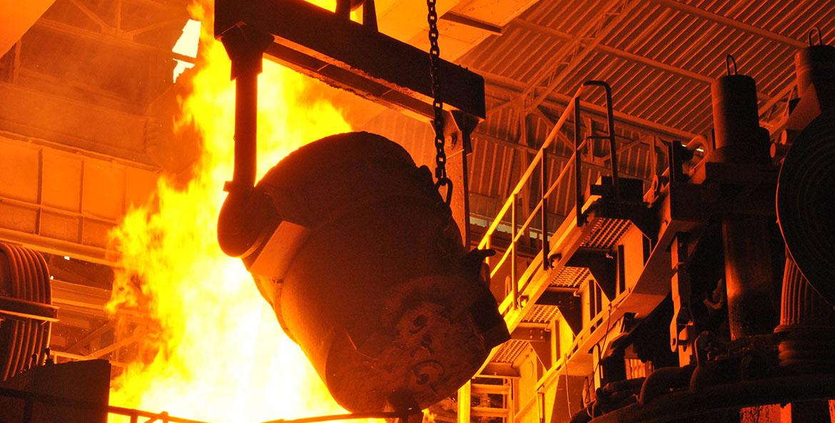
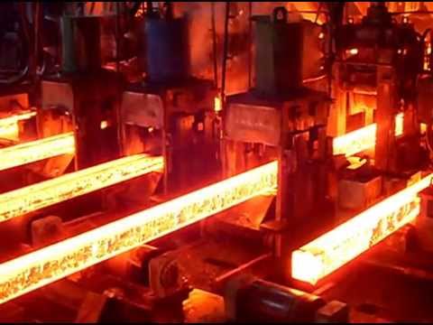
Hot Rolling Mill

Steel rolling consists of passing the material, usually termed as rolling stock, between two rolls driven at the same peripheral speed in opposite directions (i.e. one clockwise and the second anti-clockwise) and so spaced that the distance between them is somewhat less than the thickness of the section entering them. In these conditions, the rolls grip the material and deliver it reduced in thickness, increased in length and probably somewhat increased in width. This is one of the most widely used processes among all the metal working processes, because of its higher productivity and lower operating cost. Rolling is able to produce a product which is having constant cross section throughout its length. Many shapes and sections are possible to roll by the steel rolling process.

Steel sections are generally rolled in several passes, whose number is determined by the ratio of initial input material and final cross section of finished product. The cross section area is reduced in each pass and form and the size of the stock gradually approach to the desired profile.

Rolling accounts for about 90 % of all materials produced by metal working process. It was first developed in the late 1500s. Hot Rolling is carried out at elevated temperature above the re-crystallization temperature. During this phase, the coarse-grained, brittle, and porous structure of the continuously cast steel is broken down into a wrought structure having finer grain size and improved properties.

A long product rolling mill comprised of equipment for reheating, rolling and cooling. The primary objectives of the rolling stage are to reduce the cross section of the incoming stock and to produce the planned section profile, mechanical properties and microstructure of the product.


When manufacturing long products, it is common to use a series of rolling stands in tandem to obtain high production rates. The stands are grouped into roughing, intermediate and finishing stages. Typical temperature, speed, inter-stand time (time between each stand), true strain and strain rate ranges at each stage are shown in Tab 1. Since cross-sectional area is reduced progressively at each set of rolls, the stock moves at different speeds at each stage of the rolling mill. A wire rod rolling mill, for example, gradually reduces the cross-sectional area of a starting billet (e.g., 150 mm square, 10-12 meters long) down to a finished rod (as small as 5.0 mm in diameter, 1.93 km long) at high finishing speeds (up to 120 m/sec).

Tab 1 Typical parameters at rolling stages
         
  Unit Roughing Intermediate Finishing
Temperature range Deg C 1000-1100 950-1050 850-950
Speed range m/sec 0.1-1 1-10 10-120
Inter-stand time range Milli-second 1600-10300 1000-1300 5-60
True strain range   0.20-0.40 0.30-0.40 0.15-0.50
Strain rate range per second 0.90-10 10-130 190-2000


The final dimensional quality of the rolled product is determined by the rolling stands within the finishing mill. The dimensional accuracy in the final product depends on many factors including the initial stock dimensions, roll pass sequence, temperature, microstructure, roll surface quality, roll and stand stiffness and the stock/roll friction condition.

With regards to the steel material steel, the development of the microstructure during rolling is complex and involves static and dynamic re-crystallization of austenite. From a practical point of view, the austenite grain size distribution in the rolled product is of paramount importance in controlling mechanical properties. In the roughing and intermediate stages of the rolling mill, the stock is moving slowly between the stands, such that the material has a chance to ‘normalize’ itself as a result of recovery and re-crystallization. During the finishing rolling stage, the stock is traveling at a high speed between closely spaced stands and consequently, and does not have adequate time to normalize. This lack of normalization can have a significant effect on the final microstructure and mechanical properties of the rolled product.

Since the chemical composition is fixed for specific steel grades, the requirements for a particular product that can be controlled in the rolling mill consist of geometry, mechanical properties and microstructure. The product characteristics which are controlled are the geometric shape and tolerance. These are determined from the section profile of the finished product. Mechanical properties include yield and ultimate tensile strengths, % reduction in area (ductility) and hardness. Microstructure characteristics include grain size, grain distribution, phase composition and phase distribution.

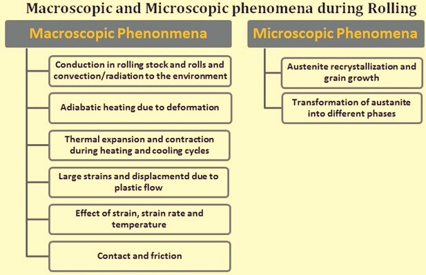
Rolling involves macroscopic and microscopic phenomena (Fig 1). The macroscopic phenomena can be broadly classified as (i) heat flow during rolling, and (ii) deformation under application of rolling load. The macroscopic phenomena include such factors as given below.


  • Conduction in the rolling stock and the rolls and convection/radiation to the environment
  • Adiabatic heating due to deformation
  • Thermal expansion and contraction during the heating and cooling cycles.
  • Large strains and displacements due to plastic flow
  • The effects of strain, strain rate and temperature
  • Contact and friction

The process at the microscopic level involves many complex physical phenomena associated with nucleation and evolution of the microstructure. The principal microscopic phenomena that are important during the process of rolling are (i) austenite re-crystallization and grain growth, and (ii) transformation of austenite into ferrite, pearlite, bainite and martensite (and/or other phases).


Fig 1 Macroscopic and microscopic phenomena during rolling

The spread and side free surfaces are very important in rolling. Spread is defined as the dimension of the deformed stock after rolling in the direction perpendicular to the direction of rolling. It measures the increase of width of the stock due to the rolling deformation. The side free surface is defined as the region of the stock surface that does not come into contact with the rolls during the rolling process. The surface profile of a deformed stock depends on the spread, free surface profile, and the elongation of the stock. This means that the final shape of the stock is mainly dependent on these parameters. Since the final shape of the stock is very important for the rolled product, these parameters are very crucial to a roll pass designer when designing a particular rolling pass for specific shape and size requirements. Accuracy in calculating these parameters are critical when satisfying such geometric requirements as roundness (in case of bars and rods) and tolerance. Roundness is defined as the difference between maximum diameter and minimum diameter. Tolerance is the allowable difference in maximum / minimum dimensions with respect to nominal dimensions.

The mean effective plastic strain is extremely important for predicting and controlling the mechanical properties of the rolled product after rolling The mean effective plastic strain at a rolling stand is defined as the maximum average effective (equivalent) plastic strain of the rolling stock at a given mill stand during the rolling process. The microstructure evolution requires thermo-mechanical variables such as mean effective plastic strain, mean effective plastic strain rate and temperature at each rolling stands. Temperature evolution due the mechanical energy converted to heat during the deformation process is also dependent on mean effective plastic strain and mean effective plastic strain rate. Furthermore, mean effective plastic strain rate is in turn a function of mean effective strain and the process time. All of this suggests that the capability of predicting mean plastic strain is essential for controlling the mechanical properties and microstructure of the rolled product.

Calculation of roll force is important because calculation of torque and power in a rolling mill is based on calculation of roll force. Accurate prediction of roll force for grooved rolling is considerably more difficult than predicting the geometry of the rolling stock. There are essentially three problems, present during the rolling as well but somewhat easy to handle. They are (i) resistance of material to deformation, as a function of strain, strain rate and temperature, (ii) the ability to calculate the distributions of the strains, strain rates, stress and temperature in the deformation zone, and (iii) the conditions at the roll metal interface, i.e., the coefficients of friction and heat transfers.

One more important parameter of high-speed high temperature rolling is the flow-stress behaviour of the particular steel grade. Flow stress is defined, as the instantaneous yield stress or true stress of a steel defined when the steel starts to undergo continuous plastic deformation. The two principal methods for accurately obtaining the flow stress of a particular grade of steel are direct experimental results and empirical constitutive equations. Empirical constitutive equations are often derived from the regression analysis of experimental data. Typically these equations define the flow strength of a material as a function of the variable considered important.


Rolls and roll pass design

Rolls are the tools of the rolling mill and are the costliest consumable in a rolling mill. The way the rolls are used to execute their duty of deforming steel is in many cases largely determined by the roll pass design. The purpose of the roll pass design is (i) production of correct profile within tolerance limits with good surface finish (free from surface defects), (ii) maximum productivity at the lowest cost, (iii) minimum roll wear, (iv) easy working, and (v) optimum energy utilization.
The accuracy and speed of working and roll life are all related to the roll pass design and the choice of the roll material. The rolling sequence of a roll pass design is subject to the limitations applied by the rolling load, the roll strength and the torque available for rolling. Roll pass design is also to ensure that the physical dimensions and material of the roll are capable of withstanding the heaviest loads arising during the rolling sequence.
The material of the roll is important since it must be capable of withstanding loads which plastically deforms the rolling stock without itself being plastically deformed. In the rolling of hot steel, this is not a difficult problem and iron or steel rolls are suitable if they are operated at a temperature considerably lower than that of the rolling stock. The choice of roll material whether cast iron or steel (cast or forged) depends on the specific duty the rolls are to perform and the important properties such as surface toughness, resistance to thermal cracking or shock loading or hard wearing properties. The selection of any particular roll depends on production demands, initial cost, and the specific qualities required. Tungsten carbide rolls are generally used in wire rod finishing blocks and in some shape rolling applications. These carbide rolls require high quality cooling water in a narrow pH range and limited hardness.
The roll material is important to estimate the loads which the rolls must withstand. In addition it suggests what mill size is most suitable for given ranges of products so as to ensure reasonable efficiency in working the mill. Perhaps one of the most important single factors where roll life is concerned is the wear properties of the roll material.
During the hot rolling of steel, heat is transferred to the rolls. If not cooled, the heat buildup causes increase in the temperature of the roll to a temperature equal to that of the stock being rolled. At this stage the roll would also undergo plastic deformation. To remove the heat from the roll, cooling water is applied. The difficulty in the removal of the heat from the roll is the result of two factors. The first is called the coefficient of thermal conductivity and the second is the interface between the roll and the rolling stock compared to that of the cooling water and the roll. Heat is transferred by conduction, convection, and radiation.
During the contact time of the rolling stock in the pass, the hot rolling stock heats the roll due to conduction during the contact time with the roll. As a result, the temperature profile on the surface of the roll increases when in contact with the roll and then drops as the heat is absorbed by the roll body. This also means that the best place to remove the heat from the roll is immediately after the bar leaves contact with the roll. The best rate of heat removal occurs when the difference in temperature is the greatest. A typical roll cooling water delivery system consists of holes in the delivery guide for the application of water as close to the point where the rolling stock leaves contact with the roll as possible. Two half circle water pipes for each roll also deliver secondary cooling water to assure the heat of rolling does not penetrate the roll body. The application of cooling water is to be controlled so that the water does not fall on the rolling stock at the entry point to the rolls. In case it happens, it only cool the rolling stock, create steam pockets between the roll and the rolling stock, and waste water that could be better used on the other side of the roll. To minimize roll wear, roll cooling water must be applied as close to the point where the rolling stock leaves the roll. Typical pressures of cooling water are 2 kg/sq cm to 5 kg/sq cm at a flow rate of about 1.5 litres / mm per minute. The best delivery systems use tube, nozzle and spray headers to get ‘soft cooling’ at low pressure and high flow, not a hard jet that ‘bounces’ the water off of the roll.
Roll surface degradation occurs primarily due to the thermal cycling of the heating and cooling of the surface versus the relatively steady state of the subsurface and adjacent material. This creates local tension and compression as the roll moves through 360 deg of rotation. The objective of roll cooling is to minimize this cycle. The objective of roll material selection is to use materials that can tolerate this cycle without fire-cracking, crazing, or wearing prematurely. The fire-cracks developed on the roll surface are required to be removed by turning down considerable material of the roll and in the process reducing the roll diameter. This affects the roll life and increases the roll cost per ton.
It is a fact that all mill rolls eventually deteriorate and the roll passes need to be changed to achieve size control and finished product surface quality. When the roll diameter reduces to less than the minimum diameter required by the mill stand after turning down, then the roll is to be discarded.


Stand and roll guide set-up

The goal of mill and the roll guide setup is to get the first bar rolled when changing product, on the cooling bed within the tolerance so that it is a saleable product. The data required to perform this function is usually provided in two forms. One is given by the mill builders and provides information about rolls, guide parts, and other equipment that needs to be changed from the previous setup. It also includes gap settings, guide adjustments, and any special instructions. Mill floor and pulpit setup sheets also contain loop height settings, motor rpm (revolutions per minute), run-out speed, production rate, R-Factors, shear setup information and other pertinent information. To enable the fastest startup possible, the retained information should reflect the conditions at startup. That is, if the rolls are always dressed at change over, the R-Factors should be what they were the last successful rolling on new rolls. Data collected at the end of a rolling with used rolls will not be accurate when rolling on new rolls.


Tension control

In a continuous mill, speed matching the stand to achieve a constant mass flow through the mill assures a low cobble rate and fewer defects. High tension can stretch reduce the cross section of the bar making shape control very difficult. At the extreme, tension can pull the bar apart, creating a cobble. Compression of the bar between stands can create flutter creating defects, or at the extreme will cause loop growth leading to a cobble. Using the working diameter of the rolls, the roll rpm (revolutions per minute) is matched to the bar speed through the mill. As the rolls wear and the spread of the bar in the pass changes, the rpm of the stands need to be adjusted as the bar area changes. Most modern control systems modify the R-Factor as this occurs. The bar speed at each stand is calculated using the production tonnage rate for the product as a mill constant. Input values for setting mill motor speeds are production rate, roll collar diameters and roll gaps, bar areas and widths, and gear ratios. Motor speed ratings are normally checked against calculated speeds.


Yield

Yield is the measurement of production loss from furnace charge to bundled, piled, or coiled finished product. The factors that influence yield are scale loss, crop loss, cobble loss, and any other factor that reduces the weight of the finished product. When the billet is charged into the reheat furnace, it is either weighed or assumed to have a nominal weight based on its cross section and grade. As it progresses through the furnace, scale is formed that is removed at the descaler or fall off during rolling. This can amount to around 1 % to 1.2 % of the charged weight. Shears that crop the malformed front end of the bar as it progresses through the mill can remove up to 0.3 m to 0.4 m of material at each shear. After dividing the bar onto the cooling bed, a cold shear or saw cuts the bar to saleable lengths, cleaning up the variations in length. Structural mills often take an additional saw cut on piled and bundled material. All the removed material contributes to yield loss. Good figures for yield are around 97 % to 98 % for bar and rod mills, and 92 % t0 94 % for structural mills. If the product is rolled with negative tolerance and sold on nominal weight basis then the yield becomes much higher. Because of this reasons some of the rebars mills which are rolling with negative tolerance, and selling rebars on nominal weight basis are reporting a finished product yield of 100 % or more, though their nominal mill yield is normal 97 %.

Electric Arc Furnace


Here, electric arc is produced between the electrodes. This electric arc is used for melting the metal. The arc furnaces are used to produce mini steel structural bars and steel rods. The electric furnace is in form of a vertical vessel of fire brick. There are mainly two types of electric furnaces. They are alternating current (AC) and direct current (DC) operated electric furnaces.


DC Electric Arc Furnace

DC Arc Furnace is recent and advanced furnace compared to AC Arc Furnace. In DC Arc Furnace, current flows from cathode to anode. This furnace has only a single graphite electrode and the other electrode is embedded at the bottom of the furnace. There are different methods for fixing anode at the bottom of the DC furnace. The first arrangement consists of a single metal anode placed at the bottom. It is water cooled because it gets heated up fast. In the next one, the anode be the conducting hearth by C-MgO lining. The current is given to the Cu plate positioned at the bottom portion. Here, the cooling of anode is by the air. In the third arrangement, the metal rods act as anode. It is entrenched in MgO mass. In the fourth arrangement, the anode is the thin sheets. The sheets are entrenched in MgO mass.


Advantages of DC Electric Arc Furnace
  • Decrease in electrode consumption by 50%.
  • Melting is almost uniform.
  • Decrease in power consumption (5 to 10%).
  • Decrease in flicker by 50%.
  • Decrease in refractory consumption
  • Hearth life can be extended.
AC electric Arc Furnace

In AC electric furnace, current flows between the electrodes through the charges in metal. In this furnace three graphite electrodes are used as cathode. The scrap itself acts as an anode. When compared to DC arc furnace, this is cost effective. This furnace is most commonly used in small furnaces.


Construction of Electric Arc Furnace

As mentioned above, the electric furnace is a large firebrick lined erect vessel. It is demonstrated in figure 2. electric ac furnace The main parts of electric furnace are the roof, hearth (lower part of a furnace, from where molten metal is collected), electrodes, and side walls. The roof consists of three holes through which the electrodes are inserted. The roof is made up of alumina and magnesite-chromite bricks. The hearth includes metal and slag. The tilting mechanism is used to pour the metal that is molten to the cradle by shifting the furnace. For the electrode removal and furnace charging (topping up scrap metals), roof retraction mechanism is incorporated. The provision for fume extraction is also given around the furnace considering the health of operators. In AC electric furnace, electrodes are three in number. These are round in section. Graphite is used as electrodes because of high electric conductivity. Carbon electrodes are also used. The electrodes positioning system helps to raise and lower the electrodes automatically. The electrodes get highly oxidized when the current density is high.
Transformer: –
The transformer provides the electrical supply to the electrodes. It is located near to the furnace. It is well protected. The rating of large electric arc furnace may be up to 60MVA.


Working Principle of Electrical Arc Furnace

The working of electric furnace includes charging the electrode, meltdown period (melting the metal) and refining. The heavy and light scrap in the large basket is preheated with the help of exhaust gas. For speeding up the slag formation, burnt lime and spar are added to it. The charging of furnace takes place by swinging the roof of the furnace. As per requirement, the hot metal charging also takes place. Next is the meltdown period. The electrodes are moved down onto the scrap in this period. Then the arc is produced between the electrode and metal. By considering the protection aspect, low voltage is selected for this. After the arc is shielded by electrodes, the voltage is increased for speeding up the melting process. In this process, carbon, silicon, and manganese get oxidized. The lower current is required for large arc production. The heat loss is also less in this. Melting down process can be fastening by deep bathing of electrodes. Refining process starts during melting. The removal of sulfur is not essential for single oxidizing slag practice. Only phosphorous removal is required in this. But in double slag practice, both (S and P) are to be removed. After the deoxidizing; in double slag practice, the removal of oxidizing slag is performed. Next, with the help of aluminum or ferromanganese or ferrosilicon, it gets deoxidized. When the bathing chemistry and required temperature is reached, the heat will get deoxidized. Then, the molten metal is ready for tapping. For the cooling of the furnace, tubular pressure panels or hollow annulus spraying can be used.

OUR OFFICES

Get in Touch

Come and visit our quarters or simply send us an email anytime you want. We are open to all suggestions from our clients

Faridabad office

K-4011,1st Floor,Sainik Colony, Sec-49

Gujarat office

Plot no 281, survey no 171, Tulsidham society, Meghpar boruchi,Taluka-Anjar ,Gujarat Pin Code-370205

Contact

balramkrishan@pranetramspl.com

+91 129 407 4012 , 98996-53730, 98998-53730